Introduction
Our
IO expansion board is evolving, this latest V5 IO expansion shield is
now supporting Xbee. It combines our popular Xbee shield with IO
expansion shield(V4). It even supports SD card which provides the
ultimate functional expansion for Arduino so far. As its predecessor,
it supports RS485, APC220, Bluetooth communication, servo control.
Specification
- Support RS485
- Support Xbee (Xbee pro)
- Support Bluetooth
- Support APC220
- Support SD card read/write
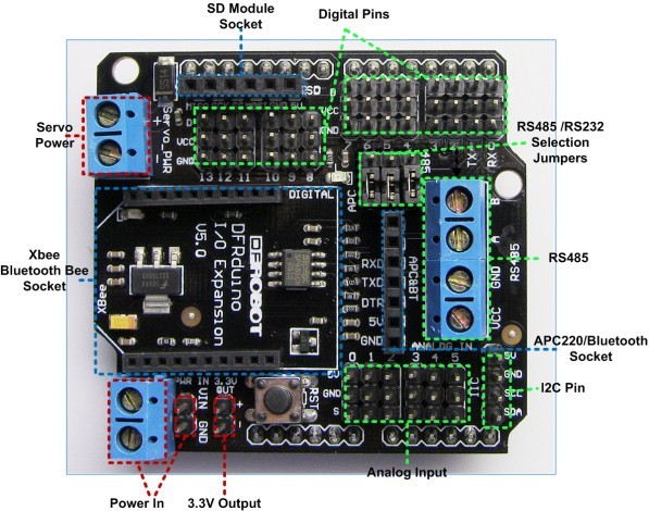
1. extension of 14 digital IO ports (12 servo interface) and power;
2.6 analog IO ports and power;
3.1 digital external power port terminal;
4. Digital-port external power supply and an onboard power supply automatic switching;
5.1 External power input terminal and an input pin;
6.RS485 interface;
7. reset button;
8.xbee/Bluetooh Bee Bluetooth wireless data transmission interface;
9.APC220/Bluetooh V3 Bluetooth wireless data transmission interface;
10.IIC/I2C/TWI interface;
11.3.3V output port;
12.SD card module interface;
RS485
It uses an SP485CN chip to handle comms.The screw terminals (assuming that the three jumpers are set to '485') marked 'A' and 'B' go directly to the IC 'A' and 'B' pins (6 & 7 respectively).
The screw terminal marked VCC goes to the IC VCC pin (8), and also to the board's +5V line (i.e. the Arduino's +5V rail).
The screw terminal marked GND goes to the IC GND pin (5), and also to the board's GND line (i.e. the Arduino's 0V rail).
The chip's DI (Data Input?) pin (4) is connected to the Arduino's Digital Pin 1 (TX).
The chip's RO (Data Output?) pin (1) is connected to the Arduino's Digital Pin 0 (RX), with a resistor pull-up to the +5V rail.
The chip's DE (output enable) pin (3) is connected (via a resistor) to the Arduino's Digital Pin 2 - this is active high.
This DE pin is also connected to the chip's RE bar (receiver enable) pin (2) and therefore controlled by the Arduino's Digital pin 2 too - this is active low.
Arduino Digital Pin 2 = Rx/Tx 'Enable'; High to Transmit, Low to Receive
So, to transmit data from Arduino Digital Pin 1 you need to take Digital pin 2 high, and to receive data to Arduino Digital Pin 0 you need to take Arduino Digital pin 2 low.
Pin Out
Sample Code
RS485 Transmit Dataint EN = 2; //RS485 has a enable/disable pin to transmit or receive data. Arduino Digital Pin 2 = Rx/Tx 'Enable'; High to Transmit, Low to Receive
void setup()
{
pinMode(EN, OUTPUT);
Serial.begin(19200);
}
void loop()
{
// send data
digitalWrite(EN, HIGH);//Enable data transmit
Serial.print('A');
delay(1000);
}
RS485 Receiving Data
int ledPin = 13;
int EN = 2;
int val;

void setup()
{
  pinMode(ledPin, OUTPUT);
  pinMode(EN, OUTPUT);
  Serial.begin(19200);
}

void loop()
{
  // receive data
 digitalWrite(EN, LOW);//Enable Receiving Data
 val = Serial.read();
  if (-1 != val) {
    if ('A' == val) {
      digitalWrite(ledPin, HIGH);
      delay(500);
      digitalWrite(ledPin, LOW);
      delay(500);
    }
 }
}
Compatibility
- Arduino UNO
- Arduino Duemilanov
- Arduino Mega 1280/2560
No comments:
Post a Comment