Arduino controlled video recording using the LANC port
LANC is a SONY development and stands for "Local Application Control
Bus". It is a two-way serial open collector 9600 baud protocol with
inverted logic. The LANC line is pulled high to about +5v and is pulled
low to send commands or status information.
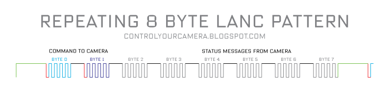
The
data stream is 8 bytes, followed by a longer than 5 millisecond pause
until the end of the current frame. Then come another 8 bytes for the
next frame and another pause and so on.
There's a short pause between individual bytes. Each byte is preceded by a start bit.
LANC is a single wire serial connection and because of this timing is
critical. The camera can only listen to commands for the first half of
the signal pattern.
The camera listens to the first 4 bytes and sends status information in
the last 4 bytes. Only the first two bytes are needed to control a video
camera. The rest can be ignored.
To
send a command to the camera the command has to be synchronized to the
LANC signal from the camera. The camera puts out a start bit before and a
stop bit after each byte. The first command byte from the controller
(Arduino) has to be transmitted exactly between the start bit that
follows the long pause between the 8 byte data packages and the
following short stop bit. Then the second byte must be send to the
camera. After sending those two bytes the LANC signal must be be left
alone and put back to LOW i.e +5V.
The
commands for starting and stopping video recording are 18 and 33 in
hexadecimal format or 00011000 and 00110011 in binary format. The bytes
must be put out with the least significant, right-most bit (bit 0) first
i.e. 00110011 is put out 11001100. Note that in a LANC signal LOW is
+5V and HIGH is 0V. LANC commands must be repeated 4 times in order to
be accepted by the camera.
Since we have to read from and write to a single wire an interface is required. Thanks to
Ariel Rocholls simple interface circuit writing and reading can be done independently. D1 is a 5.1V zener diode.
Arduino sketch:
Copy and paste it into the Arduino editor for a better reading experience.
/*
Send a Start/Sop Recording command to the LANC port of a video camera.
Tested with a Canon XF300 camcorder
This code requires a simple interface see http://micro.arocholl.com
Feel free to use this code in any way you want.

Comprehensive LANC info: www.boehmel.de/lanc.htm

"LANC" is a registered trademark of SONY.
CANON calls their LANC compatible port "REMOTE".

2011, Martin Koch
http://controlyourcamera.blogspot.com/2011/02/arduino-controlled-video-recording-over.html
*/

#define cmdPin 7
#define lancPin 11
#define recButton 2
int cmdRepeatCount;
int bitDuration = 104; //Duration of one LANC bit in microseconds.

void setup() {

pinMode(lancPin, INPUT); //listens to the LANC line
pinMode(cmdPin, OUTPUT); //writes to the LANC line
pinMode(recButton, INPUT); //start-stop recording button
digitalWrite(recButton, HIGH); //turn on an internal pull up resistor
digitalWrite(cmdPin, LOW); //set LANC line to +5V
delay(5000); //Wait for camera to power up completly
bitDuration = bitDuration - 8; //Writing to the digital port takes about 8 microseconds so only 96 microseconds are left till the end of each bit
}

void loop() {
if (!digitalRead(recButton)) {
REC(); //send REC command to camera
delay(1000); //debounce button
}
}


void REC() {

cmdRepeatCount = 0;

while (cmdRepeatCount < 5) {  //repeat 5 times to make sure the camera accepts the command

                while (pulseIn(lancPin, HIGH) < 5000) {
                  //"pulseIn, HIGH" catches any 0V TO +5V TRANSITION and waits until the LANC line goes back to 0V
                  //"pulseIn" also returns the pulse duration so we can check if the previous +5V duration was long enough (>5ms) to be the pause before a new 8 byte data packet
//Loop till pulse duration is >5ms
}

//LOW after long pause means the START bit of Byte 0 is here
delayMicroseconds(bitDuration);  //wait START bit duration

//Write the 8 bits of byte 0
//"18hex" or “00011000”  tells the camera that there will be a normal command to camera in the next byte
//Note that the command bits have to be put out in reverse order with the least significant, right-most bit (bit 0) first
digitalWrite(cmdPin, LOW);  //Write bit 0.
delayMicroseconds(bitDuration);
digitalWrite(cmdPin, LOW);  //Write bit 1
delayMicroseconds(bitDuration);
digitalWrite(cmdPin, LOW);  //Write bit 2
delayMicroseconds(bitDuration);
digitalWrite(cmdPin, HIGH);  //Write bit 3
delayMicroseconds(bitDuration);
digitalWrite(cmdPin, HIGH);  //Write bit 4
delayMicroseconds(bitDuration);
digitalWrite(cmdPin, LOW);  //Write bit 5
delayMicroseconds(bitDuration);
digitalWrite(cmdPin, LOW);  //Write bit 6
delayMicroseconds(bitDuration);
digitalWrite(cmdPin, LOW);  //Write bit 7
delayMicroseconds(bitDuration);
//Byte 0 is written now put LANC line back to +5V
digitalWrite(cmdPin, LOW);
delayMicroseconds(10); //make sure to be in the stop bit before byte 1

while (digitalRead(lancPin)) {
//Loop as long as the LANC line is +5V during the stop bit
}

//0V after the previous stop bit means the START bit of Byte 1 is here
delayMicroseconds(bitDuration);  //wait START bit duration

//Write the 8 bits of Byte 1
//"33hex" or “00110011” sends the  Record Start/Stop command
//Note that the command bits have to be put out in reverse order with the least significant, right-most bit (bit 0) first
digitalWrite(cmdPin, HIGH);  //Write bit 0
delayMicroseconds(bitDuration);
digitalWrite(cmdPin, HIGH);  //Write bit 1
delayMicroseconds(bitDuration);
digitalWrite(cmdPin, LOW);  //Write bit 2
delayMicroseconds(bitDuration);
digitalWrite(cmdPin, LOW);  //Write bit 3
delayMicroseconds(bitDuration);
digitalWrite(cmdPin, HIGH);  //Write bit 4
delayMicroseconds(bitDuration);
digitalWrite(cmdPin, HIGH);  //Write bit 5
delayMicroseconds(bitDuration);
digitalWrite(cmdPin, LOW);  //Write bit 6
delayMicroseconds(bitDuration);
digitalWrite(cmdPin, LOW);  //Write bit 7
delayMicroseconds(bitDuration);
//Byte 1 is written now put LANC line back to +5V
digitalWrite(cmdPin, LOW);

cmdRepeatCount++;  //increase repeat count by 1

/*Control bytes 0 and 1 are written, now don’t care what happens in Bytes 2 to 7
and just wait for the next start bit after a long pause to send the first two command bytes again.*/


}//While cmdRepeatCount < 5
}
I've tested the Arduino sketch with a Canon XF300 camcorder and I
suppose that the timing will work with the entire XF family. Other
cameras may require experimenting with different "delayMicroseconds"
values.
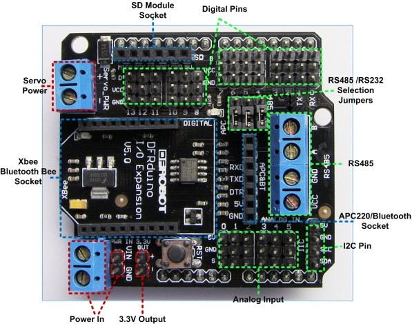
The
prototype LANC interface is built onto a shield board that sits on top
of the Arduino. The Arduino is powered by the LANC port. Although the
XF300 puts out only +5V the Arduino worked without problems. During
development I had the USB cable connected to the camera at the same time
as the Interface was connected to the camera. I suppose since the
Arduino chooses automatically to use either the external or the +5V USB
power supply this should be safe.
Always turn the camera off before plugging or unplugging the LANC cable!
"LANC" is a registered trademark of SONY.
CANON calls their LANC compatible port "REMOTE".
Comprehensive LANC info can be found at
boehmel.de/lanc.htm
31 comments:


Thanks