Monday, December 29, 2014

F2AS

A recent addition is an F2AS body, a DS1 EE aperture control.  Also an MD3 motor.

I had an F2 built up in the early 70s like this and carried some combination for a few years.  I'm still looking for a cheap MD1 or MD2 motor, but this MD3 motor set showed up at a reasonable price compared to others over the Christmas week.

F2AS, 55 F1.2, MD3


rear view showing MD-3


Above shows the F2AS with the DS-1 installed.


Seller sold the DS-1 with the box matching the serial of the unit inside.  Original sale price marked at $444, which fits with what I had to pay back in the day.

I think I had $1500 bucks into a new unit and was lucky to get out of it for what I had in it at the time after carrying it for a while.

DS-1 seems to move with a fresh battery purchased with new stock.  new battery is NMH, rather than NiCad which means it carries 330 mah rather than 220 mah that the original NiCad could hold.

I'm not sure I'll pick up the charger, since it is way over prices as a curio.  The battery isn't too hard to charge with a current limited bench supply, and I have the curves for charging the thing.  I may see about making a 4.5v current limited supply to charge it.


Sunday, November 2, 2014

Readynas Infrant 1100 and NV+ power supplies. Original Documents for 1100

A link for the original Readynas 1100 cd from infrant is here.


The original documents are scanned there as well.

2014-1103 Update:  Managed to find and buy an exact NOS replacement of this supply.  Once it arrives will update on what has to be modified to get it to match this installation.  I could verify the brown and purple wires on it (whatever they are) on the replacement.  Replacement had leads to connect to floppy / HD / SATA.  Also had the booster +5 (Black and Yellow) extra pins for the connector for P4 boards.

2014-1114 Update:  NV+ power supply.

NV+ power supply seems to be the same form factor.  Here are a couple of good photo links to the details of that supply.

These photos are taken from ones by a posting by Tom Neilsen in 2008

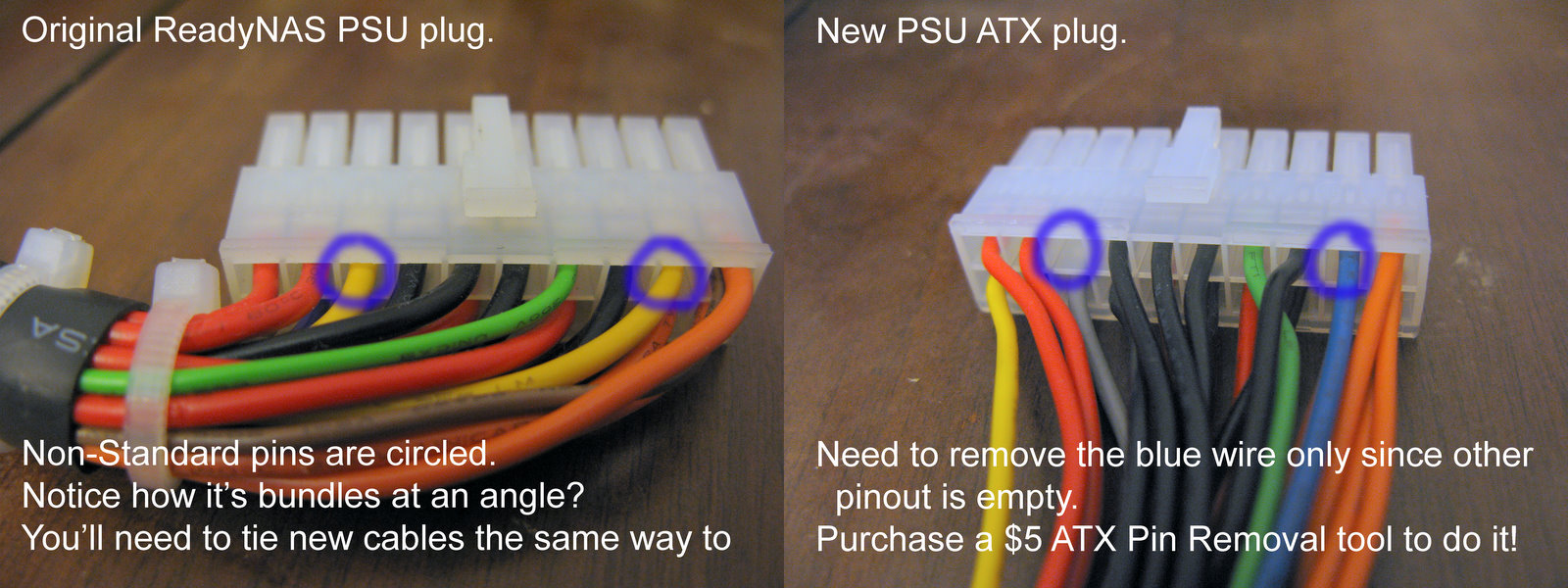
This is a good photo showing the mod needed from a normal ATX supply


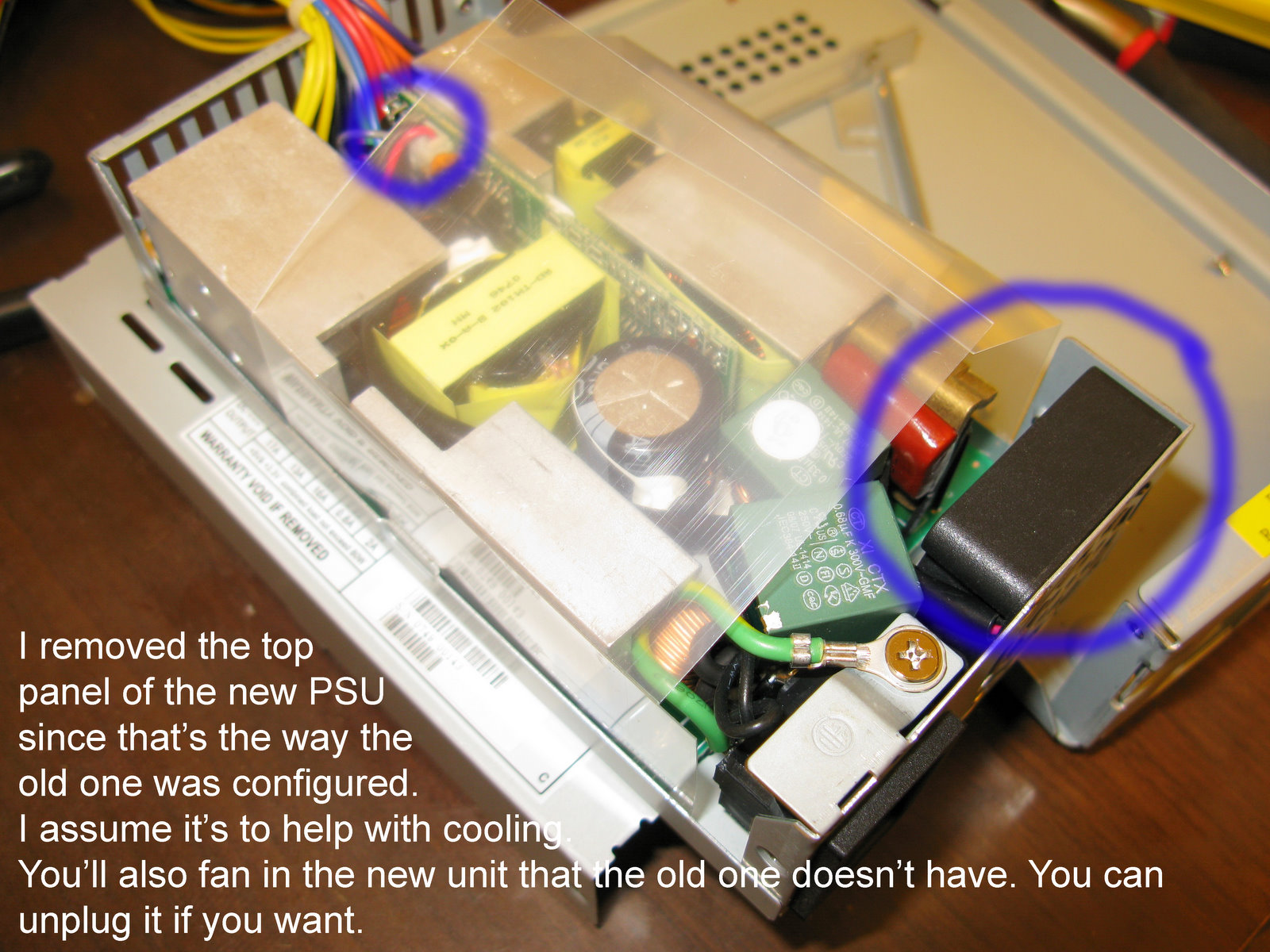
This shows the "new" power supply that can be used to replace the NV+ supply.  It is the same supply as the 1000.  However, it must have the cover removed, and the fan removed.  I don't know how this guy did with that arrangement.

There is no bulkhead cutout for the supply.  However the footprint matches the one that Infarant / Netgear used.


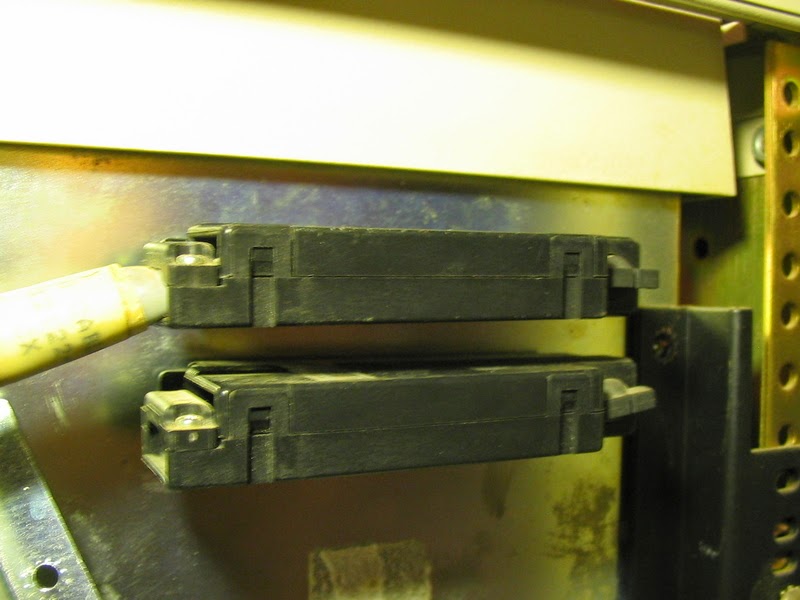
Below is a comparison of the two supplies.  Mine matches the "Old" one below, and the new one will match the New one.

At the bottom will be the entire post copied from Netgear's Readynas support site.


Photos of the power supply in 1100 are here.

Now a search for a replacement in 2014 November.


Power supply label

Power connector to board

Readynas 1100 system board
 Green heatsink covers main system board.  A USB memory stick must contain the boot information for the basic boot.  The board has what looks to be a 64 bit PCI connector, but only the middle portion is connected to anything on the disk array card.
 Memory Sim.  Looks to be laptop type card.
 Boot USB stick.
 Power connector views.  Will use to correlate to new replacement supply


 Shot with a flash for better color recognition.


Update:

The power supply that came was an exact match for the label, but had a couple of extras.

There was a normal "floppy' cable with 5 and 12 v feeds both wired up, as well as the extra 4 pin P4 booster for +12.

There were 4 pins to pull from the extra molex connector, and one from the main 20 pin connector.

An additional 12v line had to be pulled from the booster connector block an moved to an open hole on the 20 pin main connector.  And one pin had to be pulled and replaced with ground.

Besides that, I pulled all of the pins from the 4 pin flyer cable.

i'm leaving the sleeving off the wire bundle as well.  Another posting concerned pulling all 20 pins and putting the cable bundle thru a braided sleeve.  I am not going to do that.

The hint about pulling molex pins that turned out to be the most useful was one which suggested using a couple of regular office staples.

The method is as follows.  Dispense 2 staples (more if you think you will flub preparing 2). and straighten on pin out to be parallel with the back of the staple.  This gives an L shaped staple.

With a pliers or such you insert the staples on either side of a pin to be pulled from the plug side of the connector (not where the wire is, but the pin side).

seat the staple in as far as can be pushed w/o a lot of force.  It should go in to just shy of the place the block of the Molex connector is.  There are two indents there with small flaps which hold the pin in from being backed out when you plug in the connector.

Once these are released you can pull the pin from the back by the wire, and with a small wiggle it should slide out.

Reform the hold flaps and it can go into another hole in the connector and be just fine.

Here is a youtube video showing how to do it.  a movie is worth a thousand words.

http://youtu.be/9YjD_o-rDvM

Posting from Readnas Support Site showing pinouts for replacement supplies for NV+

http://www.readynas.com/forum/viewtopic.php?t=13492#p91253

I changed out my readynas PSU while waiting 4 weeks for a replacement. I documented what I did here:

I purchased an "Enhance ENP-2322B-G 220W 1U PFC RoHS Power Supply" from ebay for $36.43.

My album has more comments and observations.
http://picasaweb.google.com/trophygeek/ ... Replacment

Also, I now have an official PSU replacement from Netgear. Contact me and I'll post it to ebay for you to buy.

Image

Image

Image

Image

It's been up and working for a month now without any issues.

Thursday, October 23, 2014

IC's with dimples on covers


The photo above has packages with 4 dimples on the cover.
The package by itself at the bottom is the same, and even shares a near datecode with the above, but has no dimples.

Anyone know why the dimples?  These chips don't get hot and would not have thermal cap in operation.

And for those who want to drool, the 3 ICs with windows are Intel 1702 pulls he has.

Here are closeups of just a single package from each photo.


Tuesday, October 7, 2014

PDP 11/23 info page (translation from Swedish


Translation of:

http://www.sweclockers.com/forum/73-retro/895818-guide-hur-du-bygger-ihop-en-pdp-11-a/

More photos (not present here) are located at:

http://www.update.uu.se/~pontus/swec/

by Pontus Pihlgren

Contents: 
1. Introduction 
2. Example 
3. CPU box 
3.1 Power 
3.2 CPU card 
3.3 Memory 
3.4 Series Cord
4. Counters 
5. More current 
6. Boot Time: 

1. Introduction
Most people have at least peeked inside their PC, some might work with other machines, but how many have seen anything older than a Commodore 64? I am going to show you a look into my PDP-11 and have put together a guide that explains how to get a working system. I have restricted myself to the hardware, the software can wait for another guide. 

2. Example The system 

I chose for this guide is the fairly standard PDP-11/23 from 1979. It has two disks of model RL01, one for OS and one for data. All of this sits in a half-height 19-inch rack. At the top of the rack sits a RL01, next sits the computer case and finally the second RL01 grade. 


3. CPU box 

CPU and controls the cards sitting in a drawer of the CPU model BA-11N with PSU (model H786) and backplane (model H9273). Wait, I hear you say, what the heck is a backplane? Hold onto your hat and I'll explain it a little further down.


 In this box are already some short but it is not complete and I do not know what works: 


As I begin to empty the box completely of plug-in cards, here we see the short frame the empty Backplane: 


The backplane is what comes closest to the motherboard in this computer. It completely lacks active components and provides power and slots for other circuit board in your computer. The backplane running system bus called Qbus. Qbus: one is similar to a combination of the memory bus and the PCI bus of a PC, it is shared by the CPU, memory, disk controllers and other I / O cards. 

3.1 Power Supply 

The next step is to check if the PSU delivers what it should. I put in a short card called a BDV11. It's a mysterious thing that can be likened to a BIOS, it will sit at the bottom of the frame. On the card is a few LEDs that provide little information on what happens in the computer when it boots. To begin with, we will only concern ourselves with the green, which should be on the card is receiving power. I'm not satisfied with the lights, the voltages must be within certain tolerances and the BDV11 available data points for it, so now is the time to bring out the multimeter:


In the picture is black wire from the multimeter to the black connector on the card and the red to red contact, then measure the +5 V line, it should be within + - 5%. Then I insert the red wire in the purple plug to measure the +12 V-rope which should be within + - 3%. 

3.2 CPU card 

Now we stop at the components that make up the system. I stop at the very least you need to get a system that can communicate with a terminal. This will make it easier to isolate errors. The top of the card frame to the CPU board sit:


 In the center is an IC with two gold colored squares, it is the CPU. CPU board named KDF11 or 11/23 as it is also called. There is a 16-bit processor that is clocked at 13 MHz and can address up to 256 KW memory. Note that I write KW and not KB, it is to measure memory in number of WORD (which is 16 bits in size) when talking PDP-11. 256 KW thus equivalent to 512KB. 

All cards come from Digital Equipment has an M number that stands on the edge. KDF11 CPU has number M8186 as you see here:


 If you have a received a Qbus cards you do not know is Field Guide to Qbus and Unibus Modules indispensable, it is a list of most of the existing cards and give a brief description of their function. 

3.3 Memory 

Here is the memory for the machine: 


This card is called MSV11 and has number M8044 and is staggering 32kW memory.Not so much, but it is enough to test the system, so I start with that. The CPU I have is capable of 256KW memory but I would switch to a more modern 11/73 CPU, I get up to 4MW! But then I have to modify the backplane, which is an entirely different guide 

3.4 Series Card 

Here is an SLU, it stands for Serial Line Unit and the interface to the computer. 


This card is called DLV11 and provides four serial ports: 


It is a flexible card that can be configured with a lot of different parameters, it makes sense to go through the jumpers on the card and see what they mean in the manual. Mine is configured so that the third gate (far left) is the console port and run on the 9600 baud, 8 bits no parity and one stop bit, which is the default. 

Then CPU box ready, I put the box back in the rack and connect a terminal. 


I turn on the terminal first, then on the computer terminal see the following: 


Yes, more fun than this, it is not right now. Figure 28 is the amount of memory, measured in kW. But, you say now, you had 32 kW? Yep, but 4 kW reserved for I / O devices, so 28 is right. Now I can ask it to boot from any disk, so it will be the next step. You can also input the assembler if you are into the PDP-11 programming, but it is an extra skill. 

4. Disks 

Now I connect the two RL01 disk drives. First, I need storage controller in the CPU box, so out with it on the bench again: 


The controller is called RLV11 and comes on two boards with numbers M8012 and M8013. They're put in below the SLU card and a ribbon cableis connected:


 Flat cable is "internal" and should be routed to a connector that sits in the rack: 


Where do I plug in the external cable that will go to the controller?:


The external connector is plugged in,then engaged and locked:


 Now it should be connected to the back of an RL01 disk that has two identical connectors, the top is "in" and the other is "out". It is because the RL units connected in a chain, one after the other. Since I have two, I put the cable from the computer at the top and another cable that will advance to the next counter, at the bottom. 


To the next RL device I connect the second cable and a terminator to terminate the chain of disks. 


5. More power

Now it's just time left. In the bottom of the rack is a Power Distribution Unit (PDU), which basically is a junction box with some extra features. 


At the far left is the power in and so there are four connectors to the power to RL drives and CPU box. On the fourth one can connect the coffee machine. Far right is a small cord coming from the CPU cabinet front panels. With it, you can turn off and on the entire system, and if you look carefully you can see  that there is a blank plug to the right of it, where you can pull a cord to another rack! That way you can turn on multiple racks of equipment with just one button. And so there is a lever: 


To be able to turn on with the button on the front so it should sit on the "remote" if it is "local" so must the units power on as soon PDU plugs into the wall outlet. 

6. Boot Time! 

Now it's time to try to boot something. I intend to begin with XXDP which is a small OS with lots of software for diagnostics. RL01-disks can be described as hard drives with removable disks called disk packs. Each disc holds 5 MB and I have one with XXDP on it: 


But first I'll turn on the system because you can not open RL01 devices without power is on, this is to protect the reading head. If the power is removed when the machine is running, it is not certain that the head is parked. After a moment,  the "LOAD" lights on RL01 devices meaning they can be opened. ,


 I pull out the bottom drawer: 


And open the lid by pressing the latch on the right on the cover: 


I need to remove protection disk cover before I put it in the disk drive. I do that by lifting up the handle while I hold the lock on the handle to the left:


Then raise the handle:


 Then I put it in place of drive with the handle facing inwards:


 Then I add the disk cover on top so as not to lose it


If I do not place in the cover the computer refuses to read the disk. Finally, I close the lid on the disk drive, slide it into the rack and press the LOAD button which then goes out again. 


Now the disc starts spinning and when LOAD Indicator starts to shine again so the computer can read it. then comes the finale! I enter DL1 on screen, it means I want the machine to boot from RL01-unit number 1 And in seconds, drag XXDP ahead and ask me to talk about today's date, as you see in the picture below is not XXDP years 2000 


This concludes my guide, I hope you have become aware of some older machines, or at least have a little more appreciationl for the smooth machinery we have on your desktop today

 Merry Christmas! Edit: fixed spelling and grammar. Now is the definitive guide. 

Updated by Jim from basic Google Chrome Translate 10/7/2014
Last edited by PBGP 2009-12-13 at 20:02 .