A link for the original Readynas 1100 cd from infrant is here.
The original documents are scanned there as well.
2014-1103 Update: Managed to find and buy an exact NOS replacement of this supply. Once it arrives will update on what has to be modified to get it to match this installation. I could verify the brown and purple wires on it (whatever they are) on the replacement. Replacement had leads to connect to floppy / HD / SATA. Also had the booster +5 (Black and Yellow) extra pins for the connector for P4 boards.
2014-1114 Update: NV+ power supply.
NV+ power supply seems to be the same form factor. Here are a couple of good photo links to the details of that supply.
These photos are taken from ones by a posting by Tom Neilsen in 2008
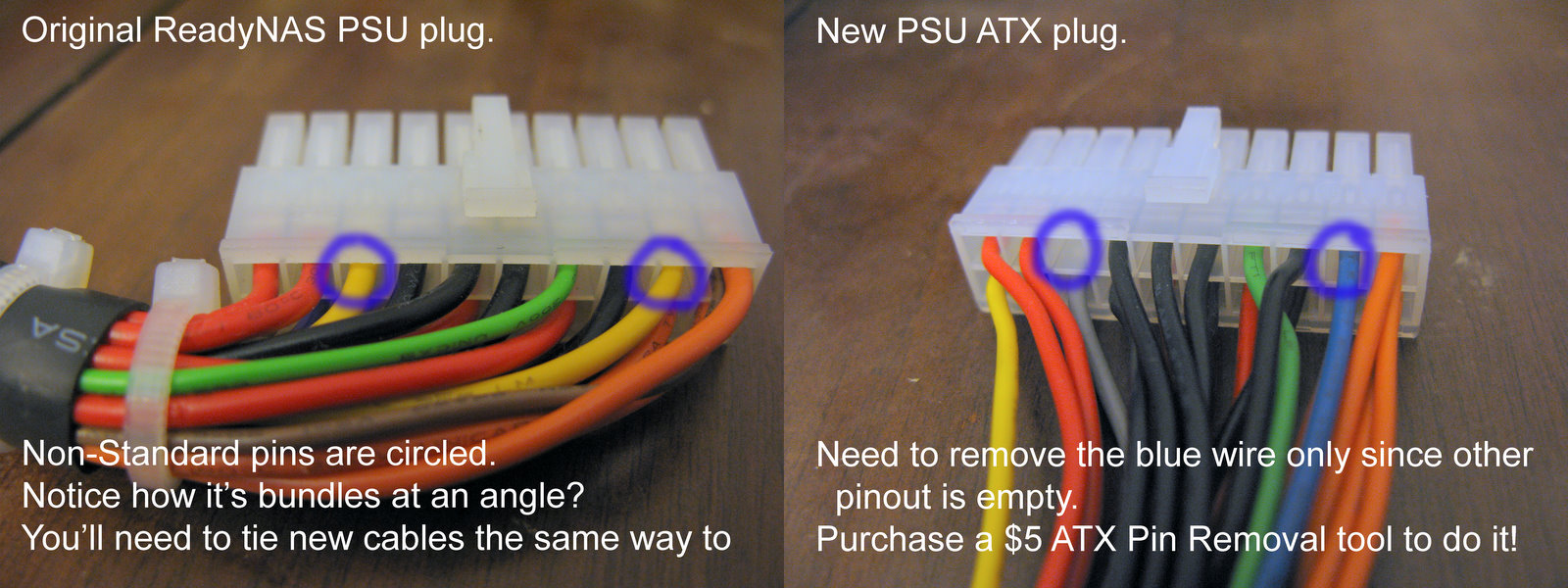
This is a good photo showing the mod needed from a normal ATX supply
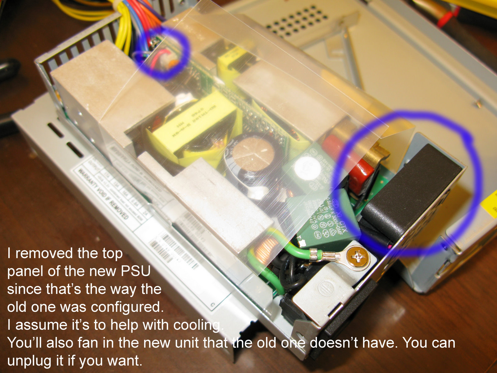
This shows the "new" power supply that can be used to replace the NV+ supply. It is the same supply as the 1000. However, it must have the cover removed, and the fan removed. I don't know how this guy did with that arrangement.
There is no bulkhead cutout for the supply. However the footprint matches the one that Infarant / Netgear used.
Below is a comparison of the two supplies. Mine matches the "Old" one below, and the new one will match the New one.
At the bottom will be the entire post copied from Netgear's Readynas support site.
Photos of the power supply in 1100 are here.
Now a search for a replacement in 2014 November.
| | | |
|
|
|
|
|
 |
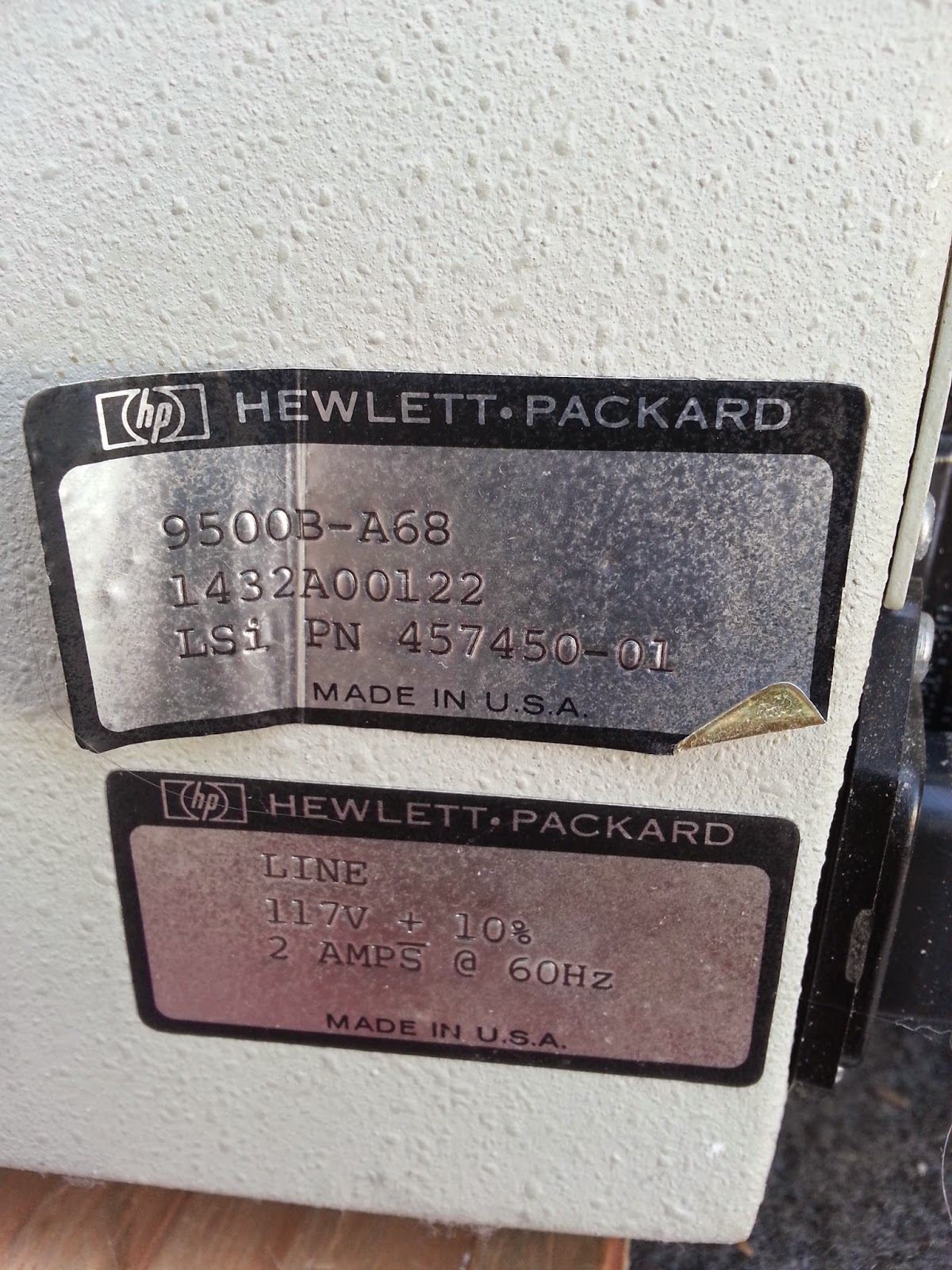
| Power supply label |
|
 |
| Power connector to board |
 |
| Readynas 1100 system board |
Green heatsink covers main system board. A USB memory stick must contain the boot information for the basic boot. The board has what looks to be a 64 bit PCI connector, but only the middle portion is connected to anything on the disk array card.
Memory Sim. Looks to be laptop type card.
Boot USB stick.
Power connector views. Will use to correlate to new replacement supply
Shot with a flash for better color recognition.
Update:
The power supply that came was an exact match for the label, but had a couple of extras.
There was a normal "floppy' cable with 5 and 12 v feeds both wired up, as well as the extra 4 pin P4 booster for +12.
There were 4 pins to pull from the extra molex connector, and one from the main 20 pin connector.
An additional 12v line had to be pulled from the booster connector block an moved to an open hole on the 20 pin main connector. And one pin had to be pulled and replaced with ground.
Besides that, I pulled all of the pins from the 4 pin flyer cable.
i'm leaving the sleeving off the wire bundle as well. Another posting concerned pulling all 20 pins and putting the cable bundle thru a braided sleeve. I am not going to do that.
The hint about pulling molex pins that turned out to be the most useful was one which suggested using a couple of regular office staples.
The method is as follows. Dispense 2 staples (more if you think you will flub preparing 2). and straighten on pin out to be parallel with the back of the staple. This gives an L shaped staple.
With a pliers or such you insert the staples on either side of a pin to be pulled from the plug side of the connector (not where the wire is, but the pin side).
seat the staple in as far as can be pushed w/o a lot of force. It should go in to just shy of the place the block of the Molex connector is. There are two indents there with small flaps which hold the pin in from being backed out when you plug in the connector.
Once these are released you can pull the pin from the back by the wire, and with a small wiggle it should slide out.
Reform the hold flaps and it can go into another hole in the connector and be just fine.
Here is a youtube video showing how to do it. a movie is worth a thousand words.
http://youtu.be/9YjD_o-rDvM
Posting from Readnas Support Site showing pinouts for replacement supplies for NV+
http://www.readynas.com/forum/viewtopic.php?t=13492#p91253
I changed out my readynas PSU while waiting 4 weeks for a replacement. I documented what I did here:
I purchased an "Enhance ENP-2322B-G 220W 1U PFC RoHS Power Supply" from ebay for $36.43.
My album has more comments and observations.
http://picasaweb.google.com/trophygeek/ ... Replacment
Also, I now have an official PSU replacement from Netgear. Contact me and I'll post it to ebay for you to buy.


 It's been up and working for a month now without any issues.